
Background
PHI-Tech Architecture were engaged by Kier to provide technical coordination services on the Tails Management Facility at Capenhurst between October 2014 to March 2017.
Working remotely, we were tasked with examining the architect’s drawings and highlight any buildability issues with the construction methods, finishes, subcontractors, cladding systems, structure, and mechanical and electrical installations.
Working closely with the architects and subcontractors, often working 9 months ahead of the construction process, PHI-Tech Architecture were instrumental in ensuring practical construction issues were minimised or avoided altogether.
As part of our remit, we were examining the architect’s drawings in a particularly sensitive area. We were concerned about the detailing of the area and whether the current details could achieve an air permeability rate of 2.
The problem
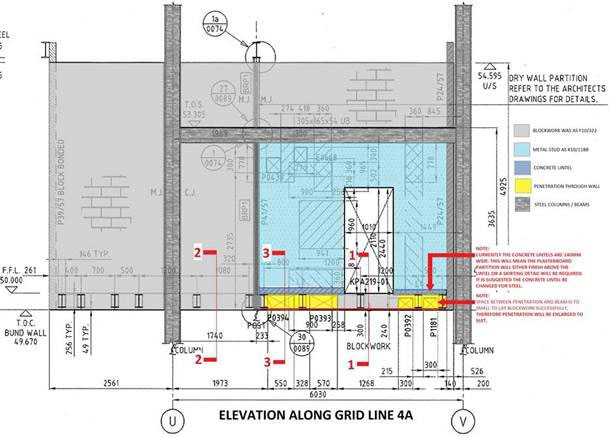
The illustration, produced 9 months ahead of construction, shows the proposed construction and highlights the issues with the design.
Colours (sketch 01) as follows,
Dark grey: concrete structure including floors and walls.
Light grey: 140 mm fair-faced dense concrete block walls.
Purple: concrete lintel.
Light blue: metal stud partition faced with plasterboard and skim.
Yellow: 140 mm fair-faced dense concrete block wall and the subject of our concern.
As you can see from the sketch, there was a clear space at the steel beams which would allow the free flow of air from room to room.
Building blockwork between HVAC and steel beams (areas indicated in yellow), some of which were only 50 – 100 mm beyond the web of the steel beam, was impractical, especially if we were to achieve an air permeability rate of 2.
The blocks were to be anchored to the tops of the bund with S/S reinforcement fixed with S/S anchors, but I couldn’t see how the reinforcement mesh will allow small pieces of concrete block to adhere the steel beam.
A 3mm metal soffit plate coated with a two-component, engineered siloxane coating, PSX700, was to be fixed to the underside of the floor deck above the block. This plate was to be the same width of the wall to allow the joint between the top of the block and the steel floor to be packed and pointed. I thought there were a few issues with this:
- If the plate was the same width of the block, it was likely the steel floor mesh would have holes which may undermine the air permeability target.
- The plate was fixed to the steel floor, which meant the floor would have to be in place before the joint packing and pointing could take place. This meant access to fill the joint would be very restricted and may not be
- The HVAC would need to be in place before the floor was fixed, which meant there would be no room below the floor for access. Perhaps more importantly, the gap between the plate and the HVAC would not be sealed. There would also be no way of sealing between the HVAC and blockwork to each side of the HVAC.
- Building what looks to be 50mm of blockwork on top of HVAC and trying to seal successfully to a rate of 2 all around the HVAC/steel beams/plates/floors would be nigh on impossible.
- There was a 140mm concrete lintel at the base of the metal stud partitions between the rooms. The partition was 155mm wide (2 x 15mm Glasroc each side of a 92 I 90 stud with insulation) which, assuming the metal base plate sits on the centre line of the lintel, means the plasterboard will not meet the floor. There were no skirtings to these walls, so we would have a very awkward detail, which may compromise the air permeability rate.
The Solution
The solution PHI-Tech Architecture came up with was very simple.
We knew what HVAC duct runs would be.
Replacing the concrete block wall (shown in yellow in sketch 1) by extending the concrete bund wall to meet the metal stud partition we could avoid laying blocks between the steel web and the ducts. The duct runs would simply be sealed against the bund wall, whilst reducing the length of the steel beams, carried out by the fabricator prior to being delivered to the site, meant the beams could be easily fixed to the face of the bund wall.